Quantcast
Channel: Moldex3d | EN
Viewing all 732 articles
Browse latest View live

GARMIN Reduced Thousands of Dollars Cost by Improving Watch Product Warpage through Moldex3D

$
0
0

Date | 2017/01/26

GARMIN Reduced Thousands of Dollars Cost by Improving Watch Product Warpage through Moldex3D

Customer Profile
garmin

As a leading worldwide provider of navigation, GARMIN is committed to making superior products for automotive, aviation, marine, outdoor and fitness markets that are an essential part of the customers’ lives. (Source: http://www.garmin.com/en-US/

Executive Summary

Waterproof is a key function in Garmin’s product design. The molding scenario has to be accurately set in order to control product deformation, air traps and product size. If the product size is not properly controlled, the watch will tend to leak under high pressure environment because of deformation. Thus, Garmin Corporation decided to utilize Moldex3D to find the optimal product design to improve waterproof.

Challenges

  • Part warpage
  • Poor waterproof due to warpage

Solutions

Utilizing Moldex3D Professional Package to obtain the optimum process settings in order to successfully improve the product’s warpage problems

Benefits

  • Reduced 2 or 3 mold revision times
  • Saved NTD$200,000 ~ NTD$300,000 worth of mold revision costs
  • Reduced 40,000pcs of the product capacity lost
  • Improved warpage by 75%
  • Improved the waterproof yield rate by 15%

Case Study

The objective of this case is to determine the gate location of a GPS watch in order to reduce the warpage problems in the middle of the part. The warpage of the original design is about 0.4mm. Garmin utilized Moldex3D to simulate the molding scenario of the original design. Through Moldex3D simulation results, Garmin found out that using traditional injection molding method, high warpage would occur in the middle of the part. This molding defect would have a direct negative impact on the product’s functionality and physical appearance. Thus, in order to solve this problem and produce high-quality products, Garmin decided to change the gate design. Therefore, they proposed two new designs of revising the gate location (Fig. 1).

garmin-reduced-thousands-of-dollars-cost-by-improving-watch-product-warpage-through-moldex3d-1
Fig. 1 The gate design revisions, Option A & B compared to the original design

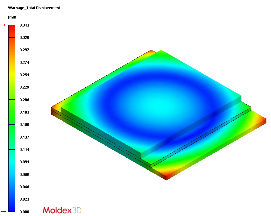
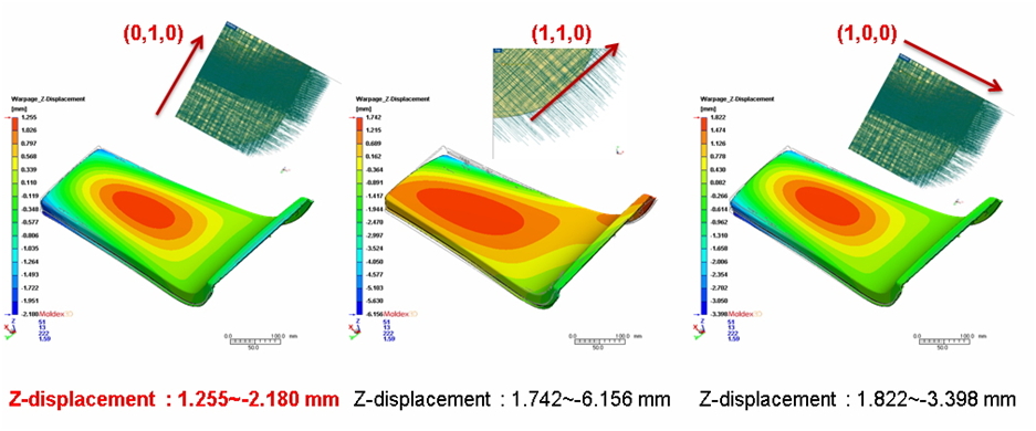
After the design changes, Garmin used Moldex3D to simulate the original design and the revised designs. The analysis results of the original product design showed (Fig. 2) the Z-axis warpage would reduce from 0.36mm (original) to 0.06mm (Option-B). And the actual mold trial results showed the warpage would reduce from 0.4mm (original) to 0.1mm (Option-B). Furthermore, Garmin found that Moldex3D simulation analysis results were strongly correlated with the results of the actual mold trials (Fig. 3).

garmin-reduced-thousands-of-dollars-cost-by-improving-watch-product-warpage-through-moldex3d-2
Fig. 2 The Z-axis warpage simulation results of 3 designs
garmin-reduced-thousands-of-dollars-cost-by-improving-watch-product-warpage-through-moldex3d-3
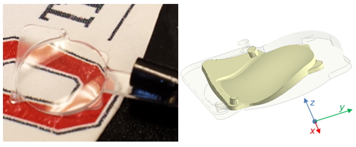
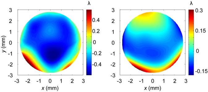
Fig. 3 The Z-axis warpage mold trials of the original and the optimized design

Results

Through Moldex3D, Garmin was able to evaluate how molding scenario affected concentricity and flatness of a watch under different gate locations and numbers. Thus, Garmin could successfully improve the flatness as well as assembly yield rate and waterproof rate. Moldex3D’s 3D mesh technology also made the simulation results more consistent with the actual results in manufacture. Ultimately, Garmin was able to decide the optimal design within limited development time, avoid repetitive mold trials, and reduce costs.


Moldex3D International Users’ Meeting 2017

$
0
0

Designing and computing plastic parts, manufacturing prototypes and series – are common tasks for all participants in the plastics processing industry. Precondition for the success of a project is a precise and solution-focused communication between the partners involved. Take the opportunity to inform yourself in detail about all the novelties and possibilities.

Due to being so visual, simulation is the language that is understood by everyone. Simultaneously, it also promotes reliable data, information and knowledge and it manages to successfully implement latest developments in future-stable solutions.

As part of our user meeting we offer you the opportunity to show your experience gathered with Moldex3D to a high-caliber professional audience in form of a user presentation.

register-now

The conference languages will be German and English. Simultaneous translators allow you to easily understand the offered content.

moldex3d-users-meeting-germany-2017-img1

Venue

Conference Centre Fortress Marienberg in Würzburg
Address: Oberer Burgweg, 97070 Würzburg, Germany

Contact

e-mail: events@simpatec.com
Tel: +49 241 565 28 28-86

ATCx: OptiStruct Conference

$
0
0

This year, CoreTech System (Moldex3D) will be attending ATCx: OptiStruct Conference taking place on February 9, 2017 at the Altair Headquarters. This event will bring structural engineers and CAE engineers together to hear about the latest product updates on Optistruct 14.0, and learn from industry experts as they discuss the cutting edge simulation solutions to overcome real-world design and manufacturing challenges. Alex Baker from Moldex3D will talk about the tight integration between Moldex3D and OptiStruct to help engineers shorten the gap between actual production and structural analyses by mapping Moldex3D injection molding simulation results to structural analysis solver OptiStruct using Moldex3D FEA Interface.

Be sure to find us at the exhibitor area and attend Moldex3D’s presentation to explore a broad range of simulation solutions provided by Moldex3D to help you open up new potential for quality and efficiency! Register Now>>

Moldex3D Speaking Session

  • Title: Interfacing Molding Simulation and Structure Analysis for Mold Design Evaluation Using Moldex3D and OptiStruct
  • Date: February 9, 2017
  • Time: 11:45 am-12:10 pm
  • Presenter: Alex Baker, Application Engineer at Moldex3D Northern American Inc.

atcx_optistruct_agenda_image_final2

Moldex3D Links 3D Injection Molding Simulation with LS-DYNA Draping Analysis to Offer a More Comprehensive Analysis for Multi-component Molding Simulation

$
0
0

Date | 2017/02/03

Continuous fiber composites give great strength to plastic products. The most common manufacturing technique of strengthening the product structure is to use laminated fabric designs because the characteristics of these fabrics not only can meet the lightweight needs but also offers high strength to the products. In recent years, along with the demand of light-weight development, manufacturers have started using continuous fiber composites in different injection molding processes.

In one fabrication, the fiber-layered prepreg is added in the mold by thermoforming as an insert. Then, a back injection is performed to attach structural functional structures to the prepreg while maintaining lightweight properties. (Fig. 1)

moldex3d-links-3d-injection-molding-simulation-with-ls-dyna-draping-analysis-to-offer-a-more-comprehensive-analysis-for-multi-component-molding-simulation-1
Fig. 1 A composite sheet product made by thermoforming and back injection

The composites molding process mentioned above is called two-step over molding. It usually consists of:  1. draping process of a fiber prepreg  2. back injection. The shaping of a prepreg is done first by soaking a dry fiber fabric in the resin under room temperature, then put it under low temperature and freeze it into a fiber prepreg. Next, the solid and flake prepreg will be moved into the mold by robotic arms, and the draping process will proceed accordingly.

The main goal of draping process is to shape the laminated fiber mat. The fiber prepreg will be heated and soften through infrared radiation, and then be compressed and solidified. After the prepreg is shaped, plastic melt will be injected into the mold. The molded product will consist of two parts: 1. continuous fiber prepreg  2. plastic molded part. A major issue in this case is to effectively predict the product properties which combine these two parts.

moldex3d-links-3d-injection-molding-simulation-with-ls-dyna-draping-analysis-to-offer-a-more-comprehensive-analysis-for-multi-component-molding-simulation-2

Fig. 2 Two step over molding process
Source : Kauss Maffei, FiberForm lightweight parts The perfect combination of thermoforming and injection moldingmbination of thermoforming and injection molding

Moldex3D R14 version has integrated with LS-DYNA’s draping analysis to simulate the deformation behavior. The fiber mat orientation of the fiber prepreg after the draping process can be considered in Moldex3D’s analysis for the subsequent molding process to obtain a more comprehensive warpage analysis of the composites product. LS-DYNA focuses on analyzing the deformation behavior of a continuous fiber in compression molding. Moldex3D will incorporate LS- DYNA’s calculation of prepreg deformation and consider the product geometry and continuous fiber mat orientation analysis as the parameters of a part insert. In Moldex3D’s filling analysis, it will consider the prepreg geometry and its material characteristics as the boundary conditions and in the subsequent warpage analysis, it will consider the insert as a continuous fiber composite material and perform a deformation analysis of a multi-component part (Fig. 3).

moldex3d-links-3d-injection-molding-simulation-with-ls-dyna-draping-analysis-to-offer-a-more-comprehensive-analysis-for-multi-component-molding-simulation-3
Fig. 3 Integrated analysis for two steps over molding process between Moldex3D and LS-DYNA

Fig. 4 is a Moldex3D’s case study example. The plastic structure part is molded on top of the fiber prepreg; Moldex3D is used to conduct the filling, packing and then the warpage analyses with the consideration of continuous fiber mat orientation.

moldex3d-links-3d-injection-molding-simulation-with-ls-dyna-draping-analysis-to-offer-a-more-comprehensive-analysis-for-multi-component-molding-simulation-4
Fig. 4 Different geometries for two steps over molding process

Through Moldex3D’s Multiple Component Molding feature, the fiber mat orientation predictions of a uniaxial prepreg in 3 different directions can be analyzed and the product’s strength variations of different directions can be attained. As shown in the analysis results, the deformation in the Z axis is the largest when the fiber mat orientation is at the angle of 45°. The least deformation occurs when the fiber mat orientations are at 0° and 90° with the deformation at 90° being the most ideal.

moldex3d-links-3d-injection-molding-simulation-with-ls-dyna-draping-analysis-to-offer-a-more-comprehensive-analysis-for-multi-component-molding-simulation-5
Fig. 5 The warpage predictions for different fiber mat orientations of prepregs

Moldex3D’s filling analysis considers the effect of chopped fiber orientation in the subsequent plastic molding process and is able to observe the influences of the plastic material and the chopped fiber orientation. In this case, the influence of the plastic material to the warpage is more significant; it causes greater shrinkage in the Y direction. When the fiber mat orientation is at 90°, the shrinkage can be compensated, making it the least deformed design.

moldex3d-links-3d-injection-molding-simulation-with-ls-dyna-draping-analysis-to-offer-a-more-comprehensive-analysis-for-multi-component-molding-simulation-6
Fig. 6 Moldex3D can predict the warpage behavior of the injected structure part

With this case, we can understand both the continuous fiber prepreg orientation and non-isotropic chopped fiber in two-step over molding will affect the product warpage. Furthermore, we find that fiber mat orientation is the main contributing factor of the product warpage. Moldex3D’s analysis provides great insights for its users in the planning of two-step over molding process and helps avoid excessive warpage to ensure the success of their composite products and assist users in maximizing their advantages.

Webinar: Understanding the Influence of Fiber on Structural Analysis

$
0
0

2017-webinar-series-web-en

Webinar: Understanding the Influence of Fiber on Structural Analysis

Structural integrity is one of the key concerns for many plastics part developers. This webinar will introduce the procedure and application by using Moldex3D’s simulation output for structural FEA analysis considering certain variables of molding process, such as fiber orientation or residual stress, and import them into the structural analysis software. Therefore, users can further evaluate advanced structural strength and impact property more accurately.

Registration

We’re offering two sessions for this webinar, so be sure to attend the one that best fits your schedule! Calculate your time zone by clicking here.

Wednesday, April 5, 2017 2:30 PM EDT Register now

Thursday, April 6, 2017 10:30 AM CEST/2:00 PM IST Register now


moldex3d-fea-interface

INTERMOLD KOREA 2017

$
0
0

Moldex3D is pleased to announce that we will be returning to INTERMOLD KOREA 2017, Asia’s leading die and mold exhibition and the largest industry event in Korea. Held together with KOPLAS and HARFKO, INTERMOLD KOREA is the best venue to witness advanced technologies and equipment from around the world.

intermold-korea-2017

This year at INTERMOLD KOREA 2017, Moldex3D will demonstrate our latest CAE simulation technologies and showcase current and future industry trends. We cordially invite you to visit our Booth M419 and find out the best solution for you to overcome your daily plastic product design challenges!

intermold-korea-2017-booth

Venue

KINTEX Center, Seoul, Korea

Contact

Vera Yeh
verayeh@moldex3d.com
+886-3-5600199 ext. 707

Moldex3D FY’17 EMEA Channel Partner Meeting

$
0
0

moldex3d-fy17-emea-channel-partner-meeting

Moldex3D is delighted to announce this year we are having our FY’17 EMEA Channel Partner Meeting in Europe! This meeting will take place on 19-20 April at NH Hotel Utrecht in the Netherlands and it’s designed to meet all your needs. In this year’s event, you will:

  • Uncover the key features and sales points of Moldex3D R15 and get geared up for the future product roadmap.
  • Meet our Team and exchange valuable experience with other Regional Partners from Europe, Middle East, and Africa.
  • Learn about the product highlights and sales techniques tailored to reflect the European market.
  • Get the latest competitor analysis and practical real-world strategies to tackle the competition challenges.

It would be a great pleasure for us to meet you all partners in one meeting and we look forward to seeing you soon in Utrecht!

Detailed agenda coming soon!

register


Venue

NH Hotel Utrecht
Jaarbeursplein, 24,
3521AR
Utrecht – The Netherlands

NH Hotel Utrecht


Contact

Vera Yeh
verayeh@moldex3d.com
+886-3-5600199 ext. 707


Registration

Please fill out the required (*) fields below.
[contact-form-7]

Webinar: What’s New in Moldex3D R15.0

$
0
0

2017-webinar-series-web-en

Webinar: What’s New in Moldex3D R15.0

Simulation can help you make quick and informed decisions in the early design phase. But problem is, simulation preprocessing is all too often time consuming and laborious. Moldex3D R15.0 offers enhanced performance, accuracy and better usability to streamline simulation workflow and provide faster turnaround times with added efficiency. Join us for this live webinar to learn about the best and newest features/enhancements in Moldex3D R15.0 that can enhance your next simulation projects and results, saving you significant time and effort. .

Registration

We’re offering two sessions for this webinar, so be sure to attend the one that best fits your schedule! Calculate your time zone by clicking here.

Wednesday, April 19, 2017 10:30 AM CEST/2:00 PM IST Register now

Wednesday, April 19, 2017 2:30 PM EDT Register now


webinar-how-to-obtain-lightweight-and-robust-design-with-simulation-technology


Moldex3D Users’ Meeting- North America 2017

$
0
0

moldex3d-users-meeting-north-america-2017-web

Moldex3D Users’ Meeting- North America 2017 is an annual event opportunity to strengthen the collaboration between Moldex3D Company and the plastic engineering community in North America region. This meeting will be the biggest event that brings together our top management, users, partners, and as well as experienced professionals working in the plastic engineering field under one roof to discuss the latest industry trends and know-how, and exchange valuable experiences to help bring your product to life. Register Now>>

The Conference on the first day will include:

  • New product updates on Moldex3D’s latest version, Moldex3D R15.0
  • Novel molding and plastic product design knowledge & technologies
  • Moldex3D’s customer’s successful case presentations
  • Interactive dialogue to shape the future developments of Moldex3D software
  • Demonstrations on Moldex3D’s new simulation capabilities
  • Plenty of networking opportunities with like-minded professionals

register-now


Featured Speakers


BASFw_wh100tr_4cBASFw_wh100tr_4cBASFw_wh100tr_4cBASFw_wh100tr_4c moldex3d-logo

BASFw_wh100tr_4cBASFw_wh100tr_4cBASFw_wh100tr_4c


Agenda

Conference Day 1: Thursday, May 4, 2017│Grande Ballroom

TIME SESSION PRESENTER
8:30 – 9:00 Breakfast/Registation
9:00 – 9:30 Vision and Future Development of Moldex3D Moldex3D
9:30 – 10:00 Advances in Compression Molding Simulation of Fiber Reinforced Thermoplastic Toyota
10:00 – 10:30 Presentation BASF
10:30 – 10:45 Break
10:45 – 11:15 Rubber Molding Process: Simulation and Experiment Validation Henniges
11:15 – 11:45 Presentation Molex
12:00 – 1:00 Lunch
1:00 – 1:30 Presentation Ford
1:30 – 2:00 Predicting Part Fit and Finish in Early Design Stage with Moldex3D Toyoda Gosei
2:00 – 2:30 (TBD)
2:30 – 2:45 Break
2:45 – 3:15 Presentation Denso
3:15 – 3:45 (TBD)
3:45 – 4:15 (TBD)
4:15 – 4:45 Presentation Moldex3D
4:45 – Cocktails & Networking

.

Demo Day 2: Friday, May 5, 2017│Galilee Room

TIME SESSION PRESENTER
8:30 – 9:00 Breakfast/Registation
9:00 – 10:30 Demo
10:30 – 10:45 Break
10:45 – 12:00 Workshop and Wrap Up

.
The 2nd day will be a workshop and demo of our latest release, Moldex3D R15.0.  Seats are limited and participants will be provided with a 3-month trial license to fully understand and experience our capabilities hands-on. To join, please select “ full Event (May4-5)” upon registration below.


Venue

The Inn at St. John’s
44045 Five Mile Rd., Plymouth, MI 48170 (Click here for a map.)

Day 1 – Conference will be held at the Grande Ballroom located at the rear end of the property. Ample space is provided at the Grand Ballroom Parking area.

Day 2 – Demo will take place inside the Galilee Ballroom.  You may park in the front and proceed thru the Conference Center Entrance. (View Floor Plan).

The-Inn-at-St.-John's

Contact

Kiki Kratzer
248-946-4570 ext. 327
kikikratzer@us.moldex3d.com


Registration

*Please answer completely. To join the demo and receive a 3-month Moldex3D R15.0 trial license, please select “Full Event (May 4-5).”

[contact-form-7]

The Latest Release of Moldex3D R15.0 Streamlines Simulation Workflow to Provide Faster Turnaround for Plastic Part Designs

$
0
0

Hsinchu, Taiwan – March 8, 2017 –CoreTech System (Moldex3D), the global leading provider of plastic injection molding simulation solutions, today introduced the latest release of Moldex3D R15.0. This newest version offers enhanced performance, accuracy and efficiency to streamline simulation workflow and provide faster turnaround times.

Reducing Pre-processing Time & Effort
One of the most significant improvements in Moldex3D R15.0 is the reduction in pre-processing time and effort. The new runner meshing technology enables automatic generation of high-resolution hexahedral meshes and offers various node types for line runner connections to better capture the intended geometric shape of the runner design and deliver more accurate predictions.

Also, the extended non-matching mesh technology supports the automatic meshing of mold components to be non-matched, such as the interface between part and part insert/mold base in order to obtain accurate simulation results with minimal effort.

Streamlining Simulation Workflow in One Integrated Platform
Moldex3D Studio is a fully integrated platform that streamlines all phases of the simulation workflow, from pre-processing to post-processing onto one intuitive, ribbon-style interface. The new platform complements the current Moldex3D Designer and Moldex3D Project applications and enables users to display and compare simulation results of multiple designs simultaneously to shorten the product development time.

Obtaining Optimal Accuracy through Fully Coupled Process Simulation
The fully coupled process simulation is a pioneering breakthrough in Moldex3D R15.0. Users can now take advantage of the new coupling technology which can simultaneously utilize Flow/Pack/Cool/Warp solvers to obtain optimal accuracy for simulating products of complex geometric designs or advanced manufacturing process like Rapid Heat Cycle Molding (RHCM).

Simulating New Process Applications
Moldex3D R15.0 also provides new simulation capabilities for In-mold Decoration (IMD) and Polyurethane (PU) chemical foaming process. The boundary condition application in the pre-processor of In-mold Decoration (IMD) simulation is made available the first time in commercial mold-filling analysis software to provide a quick and easy approach to meshing the decoration layers for simulation. Moreover, the “wash-out Index” feature enables designers to better predict washout of the ink of the decoration film to ensure successful decorative products.

The new addition of polyurethane (PU) foaming simulation supplements Moldex3D’s capabilities for chemical foaming processes; In addition to the existing microcellular foaming analysis for thermoplastics, PU foaming simulation provides part designers an ability to check the density distribution and ensure a desirable volume-to-weight ratio of the final part.

In addition, the enhancements in compression molding analysis enable a more accurate simulation for SMC materials, going from solid to molten and back to solid state, through a tighter integration between Moldex3D and LS-DYNA.

Bridging the Gap between Simulation & Shop Floor
The machine interface are further expanded to include over 15 mainstream injection molding machine manufacturers to shorten the gap between the predicted and real-life parameters.

Managing the Big Data for Effective Simulations
The new Intelligent Simulation Lifecycle Management (iSLM) solution provides an effective management of vast volumes of simulation data, giving teams at different geographic locations within an organization one single point of entry to store, share, and re-use simulation data in a safe and centralized environment.

“Moldex3D is devoted to improving its software’s functionality and simulation accuracy in each release,” said David Hsu, President of Product Development at Moldex3D. “With the new features and enhancements in Moldex3D R15.0, we aim to provide a high-performing CAE analysis with greater accuracy and efficiency to help users design and manufacture high-quality plastic parts with faster turnaround times which truly gives them an ability to keep an edge over competition and achieve excellent results.”

Moldex3D R15.0 is available now. For pricing and detailed product features, please contact your local resellers or sales representatives. Further information about Moldex3D R15.0 also can be found on the Moldex3D R15.0 Launch Page.

About CoreTech System (Moldex3D)
CoreTech System Co., Ltd. (Moldex3D) has been providing the professional CAE analysis solution “Moldex” series for the plastic injection molding industry since 1995, and the current product “Moldex3D” is marketed worldwide. Committed to providing advanced technologies and solutions to meet industrial demands, CoreTech System has extended its sales and service network to provide local, immediate, and professional service. CoreTech System presents innovative technology, which helps customers troubleshoot from product design to development, optimize design patterns, shorten time-to-market, and maximize product return on investment (ROI). More information can be found at www.moldex3d.com.

SAEILO Seminar: Moldex3D CAE Workshop

$
0
0

WORKSHOP ที่จะทำให้่คุณใช้โปรแกรม CAE เป็นภายใน 1 วัน เพื่อกำจัดตรวจสอบปัญหาเหล่านี้ในแม่พิมพ์

  1. SHORT SHOT ปัญหาฉีดไม่เต็ม
  2. WELDLINE ปัญหารอยเชื่อมประสาน
  3. UNBALACE FLOW ปัญหาการไหลที่ไม่สมดุล
  4. SINK MARK ปัญหายุบของชิ้นงาน

register-now


การสัมมนาเชิงให้คำปรึกษาในครั้งนี้มีความมุ่งหมายเพื่อที่ให้ ผู้เข้าร่วมอบรมสามารถ

  1. ผู้เข้าร่วม workshop เข้าใจหลักการการใช้งานและขั้นตอน software ประเภท CAE ที่เหมาะสม
  2. ผู้เข้าร่วม workshop สามารถอ่านผลของโปรแกรมและสรุป เพื่อค้นหา
    ปัญหาฉีดไม่เต็ม ปัญหารอยเชื่อมประสาน ปัญหาการไหลที่ไม่สมดุล ปัญหาการเปลี่ยนแปลงของความดัน
  3. สามารถนำ Software กลับไปใช้งานได้อย่างมีประสิทธิภาพที่บริษัทและใช้เป็นแนวทางแก้ปัญหาได้

กำหนดการ

Time Topic
08:30 – 09:00 ลงทะเบียน
09:00 – 09:30 สาเหตุของปัญหาฉีดไม่เต็ม SHORSHOT การไหลที่ไม่สมดุล
10:00 – 11:00 การสร้าง Mesh ที่เหมาะสมสำหรับงาน CAE
11:00 – 12:00 การตั้งค่าการเพื่อคำนวณ CAE ที่เหมาะสม
12:00 – 13:00 พักรับประทานอาหารกลางวัน
13:00 – 14:00 การอ่านค่าผลการคำนวณ CAE ที่ได้เพื่อตรวจสอบ Short shot, Weld line, Unbalance, Pressure drop
14:00 – 14:45 หลักการนำผลจากทีได้จากโปรแกรมไปแก้ไขการออกแบบ
14:45 – 15:30 ศึกษาผลจาการปรับแก้ปัญหาก่อนหน้า
15:30 – 16:00 ถามตอบ

วิทยากร

Mr. Paul Tsai และ เจ้าหน้าที่จาก Moldex Thailand
โดยคุณ Paul Tsai ซึ่ง มีประสบการณ์เชี่ยวชาญกว่า 30 ปี อยู่ในวงการอุตสาหกรรม
การผลิตรถยนต์ มีความเชี่ยวชาญเฉพาะด้านครอบคลุมทางด้านผลิตภัณฑ์พลาสติก
ออกแบบแม่พิมพ์ และการเพิ่มประสิทธิภาพการผลิต

จำนวนผู้เข้าอบรม
จำนวนผู้เข้าอบรม 5 ท่าน

Location

โมลด์เด๊กซ์ทรีดี สำนักงานใหญ่ ตึกเมืองไทยภัทรประกันภัย
252/124 ยูนิต (จี) ชั้น 26 อาคารเมืองไทย-ภัทรคอมเพล็กซ์ อาคาร 2
ถ.รัชดาภิเษก แขวงห้วยขวาง เขตห้วยขวาง กรุงเทพมหานคร 10310


Contact

รายละเอียดเพิ่มเติม ติดต่อ คุณเอกภัทร์ สุธาอรรถ
โทร 083-709-3928
Email : akekapat@saeilo.co.th
เบอร์แฟ็กซ์ 02-061-5570


Registration

[contact-form-7]

Innoform 2017

$
0
0

Moldex3D is pleased to announce that along with our local partner, PawForm, we will be exhibiting at INNOFORM 2017 in Bydgoszcz, Poland from 25th to 27th in April.

innoform

INNOFORM 2017 will be an excellent business platform and a place where manufacturers, distributors and scientists can exchange knowledge and experience with professionals in related fields. Moldex3D cordially invites you to visit us at our Booth #21 in Hall 2 to discuss the latest injection molding simulation technologies and explore the possible solutions to your plastic product design challenges.

Venue

Bydgoszcz Trade and Exhibition Centre
Gdanska 187 Str. 85-684 Bydgoszcz, Poland

innoform2

Contact

Vera Yeh
verayeh@moldex3d.com
+886-3-5600199 ext. 707

Molding Innovation Day 2017- CSoft, Moscow

$
0
0

molding-innovation-day-2017-csoft-moscow

Moldex3D together with our local partner CSoft is pleased to introduce our Molding Innovation Day at Holiday Inn Moscow – Sokolniki in Moscow on 25th April, 2017. Technical presentations and discussion on the most up-to-date injection molding simulation applications will be the main focus of this seminar. Also, Moldex3D Regional Manager, Vincent Hung will be our highlight speaker to showcase the new powerful features of Moldex3D’s latest R15 version, helping you gain valuable insights and revolutionize your productivity. Make sure you book the date!

Agenda

Time General Session Speaker
09:30-10:00 Registration
10:00-10:10 Greetings from the organizers of the seminar. Barvinsky I., Csoft
10:10-11:10 New release Moldex3D R15 Simulation of viscoelastic behavior in thermoplastics injection molding and annealing of molded parts. Hung V., CoreTech System (Moldex3D)
11:10-11:45 New injection molding engineering thermoplastic compounds based on polyphenylene sulfide. Kiselev S. obylichenko D., POLYPLASTIC
11:45-11:50 Break
11:50-12:25 Features of injection molding of thick-walled parts. Barvinsky I., Csoft
12:25-13:00 Thermostability of thermoplastic material in the hot runner injection molding. Duvidzon V.,
AB Universal
13:00-13:45 Lunch
13:45-14:15 Efficient mold cooling for precision injection molding of thermoplastics. Duvidzon V.,
AB Universal
14:15- 14:45 Prediction of the cycle time at injection molding of thermoplastics. Zubkov S., Mavrin A., POLYPLASTIC
14:45-15:15 Injection molding of polyphenylene sulfide. Barvinsky I., Csoft
15:15-15:35 Coffee Break
15:35-16:05 Injection molding of glass fibers filled thermoplastic compositions. Barvinsky I., Csoft
16:05-16:35 Selection of design solutions of two-component injection molding. Duvidzon V.,
AB Universal
16:35-17:15 Consultations on the plastics molding troubleshooting.

Venue

Holiday Inn Moscow – Sokolniki
Rusakovskaya Ulitsa 24, Moscow, 107014 Russia

molding-innovation-day-2017-csoft-moscow-venue

Contact

  • Igor Barvinsky
    Tel. + 7 495 913 22 22 ext. 2264
    Mob. +7 916 216 91 01
    E-mail: ibarvinsky@csoft.ru

Utilizing CAE Tools to Overcome the Challenges of Multi-cavity Co-injection Molding

$
0
0

Date | 2017/03/23

Multi-cavity co-injection molding is one of the most commonly used processes to manufacture automotive components and structural reinforcement products, and it has been widely applied in many industries. The benefits of multi-cavity co-injection molding include the ability to reduce material waste and cost, and further enhance the productivity of co-injection molding parts.

However, the same general guidelines for developing a single-cavity co-injection mold cannot be fully applied in the development of a multi-cavity co-injection mold. The key to a successful multi-cavity co-injection mold is proper core/skin distribution. The co-injection molding is already a complex process itself. By combining multi-cavity molding process, which often results in flow imbalance, it would be very difficult to achieve the desired distribution of materials.

Moldex3D, a computer-aided engineering tool, is often used to predict potential molding issues and analyze the intricate mechanism of multi-cavity co-injection molding system. The following case study illustrates how Moldex3D is used to evaluate the effects of injection flow rate and cavity design for designing a better multi-cavity co-injection mold.

The runner geometries and the cavity used in this multi-cavity co-injection simulation experiment are shown in Fig. 1. The material of the core and skin is POLYREX®PG-22. In the molding process, a certain percentage of skin is injected first, and then the core material is injected to finish the filling process. The skin to core ratio is 72:28.

utilizing-cae-tools-to-overcome-the-challenges-of-multi-cavity-co-injection-molding-1
Fig. 1 The cavity and the runner geometries used in the multi-cavity co-injection molding experiment

The comparison of the simulation and experimental results of the core layer melt front is shown in Fig. 2 according to the study. As shown, at a low injection flow rate (10.2 cm3/S), Branch 1 has the longest core penetration distance, while at a higher injection flow rate (51 cm3/s), Branch 2 is the longest. Both simulation and experimental results show similar trends.

utilizing-cae-tools-to-overcome-the-challenges-of-multi-cavity-co-injection-molding-2
Fig. 2 The blue lines show the melt front result measured in the experiments, and the colored red area is the melt front simulation result.

The following experiment was designed to further investigate the effects of different injection flow rates on the low-viscosity core material penetration. As shown in the analysis results, when the injection flow rate is at 10 cm3/S, the core material in Branch 1 reaches the cavity first. When the injection flow rate increases to 16 cm3/S, the core material in Branch 2 reaches the cavity first. Moreover, as the injection flow rate further increases, the proportion of the core material in Branch 1 decreases. The reason is that more core materials flow into the second and third cavities due to the high shear stress.

utilizing-cae-tools-to-overcome-the-challenges-of-multi-cavity-co-injection-molding-3
Fig. 3 Simulation results of different injection flow rates

However, the core material penetration simulation results cannot guarantee ideal skin/core distribution can be achieved in the final molded part. Fig. 4 shows unbalanced skin/core distribution in each cavity, regardless of high or low flow rate, since the first cavity has been filled at the earlier stage.

utilizing-cae-tools-to-overcome-the-challenges-of-multi-cavity-co-injection-molding-4
Fig. 4 The melt front simulation results of core material: (a) 81% filling; (b) 100% filling

Thus, in order to efficiently manage the skin/core distribution of the final molded part, it is necessary to take the effects of mold design into consideration. As shown in Fig. 5, if we modify the angles of the runners to a more symmetrical design, we can obtain a more uniform skin/core distribution (Model 2). If the runner design cannot be modified, we can modify the cavity design. Adding an overflow region or adding a connector between each cavity can both improve flow imbalance (as shown in Fig. 3).

utilizing-cae-tools-to-overcome-the-challenges-of-multi-cavity-co-injection-molding-5
Fig. 5 The influence of different mold design

In summary, the dynamic behavior of core material penetration in multi-cavity co-injection molding is a complicated issue, involving many factors such as flow rate, material properties and mold design. Influenced by the interactions between these factors, it is difficult to achieve a uniform distribution by simply changing the process condition parameters. Therefore, utilizing Moldex3D as a CAE tool has become a much more efficient way to quickly identify and fix potential issues prior to manufacturing and it can also benefit the development of multi-cavity co-injection molding technology.

Reference:

  1. Wikimedia Commons, Website information: http://commons.wikimedia.org/wiki/File:Co-injection_(sandwich)_molded_part.jpg, Accessed: Nov. 25, 2014.
  2. Yang, W.M., and Yokoi, H., “Visual analysis of the flow behavior of core material in a fork portion of plastic sandwich injection moulding”, Polymer Testing, 22, pp 37-43 (2003).
  3. Job, S., “Recycling composites commercially”, Reinforced Plastics, pp, 32-38, Sep/Oct. 2014.
  4. Pimenta, S., and Pinho, S. T., “Recycling carbon fibre reinforced polymers for structural applications: Technology review and market outlook”, Waste management, 31, pp 378-392 (2011).
  5. Jackie Yang, Chao-Tsai (CT) Huang, Hsien-Sen Chiu, Jimmy C.Chien, and Anthony Wen-Hsien Yang, “Dynamic Behavior of Core-material Penetration in Multi-Cavity Co-Injection Molding”, SPE ANTEC Tech. Paper, Paper No. 2096345, 1-5 (2015).

Moldex3D Supports Orthotropic Material Setting to Allow Consideration of the Effect of the Previous Shot in MCM

$
0
0

Date | 2017/03/23

The draping process will change the fiber orientation of the orthotropic prepreg, and further affect its mechanical property and warpage behavior. Modex3D Multi-component module (MCM) module supports orthotropic material setting of part inserts and allows users to consider the effect of the previous shot. Applying project method or existing orthotropic material data, the mechanical property affected by the orientation of continuous fiber in the prepreg can be considered in details in the simulation.


Step 1.  To assign orthotropic material of the part insert, go to MCM tab in Computation Parameter of the MCM project. Under the tab, click Settings under Orthotropic Material Properties to launch the workspace and assign or modify the orthotropic material property. The option, User-defined properties will show up if any orthotropic material has been assigned.

moldex3d-supports-orthotropic-material-setting-to-allow-consideration-of-the-effect-of-the-previous-shot-in-mcm-1


Step 2.  In the workspace, users can create orthotropic material data to part insert. Click moldex3d-supports-orthotropic-material-setting-to-allow-consideration-of-the-effect-of-the-previous-shot-in-mcm-2 Create property and select the target part insert mesh, and specify the property name and two directions of principle axis. By expanding the dialog, users can modify mechanical and expansion parameters in each axis direction.
Note: The principle axis is the two main orientations of the part insert material before prepreg.

moldex3d-supports-orthotropic-material-setting-to-allow-consideration-of-the-effect-of-the-previous-shot-in-mcm-3

  • To import orthotropic material data, click moldex3d-supports-orthotropic-material-setting-to-allow-consideration-of-the-effect-of-the-previous-shot-in-mcm-4 Import property, select target material data, and select a part insert mesh to assign it.
  • To delete orthotropic material data, click moldex3d-supports-orthotropic-material-setting-to-allow-consideration-of-the-effect-of-the-previous-shot-in-mcm-5 Delete property and select a property item to remove it.
  • To re-assign orthotropic material to different part insert, right click property item and click Modify part insert, and select a different part insert mesh.
  • To modify orthotropic material properties, right click property item and click Edit property.

moldex3d-supports-orthotropic-material-setting-to-allow-consideration-of-the-effect-of-the-previous-shot-in-mcm-6


Step 3. Click moldex3d-supports-orthotropic-material-setting-to-allow-consideration-of-the-effect-of-the-previous-shot-in-mcm-7 to go back to Project. User-defined properties will be checked. Then, click OK to finish the settings and run analysis.

Step 4. For two-shot molding, users can use the same orthotropic material setting on the same prepreg insert for the second shot. Under MCM tab in Computation Parameter, check Link with previous shot and specify the project and run number as the resource of part insert data from the previous shot.

moldex3d-supports-orthotropic-material-setting-to-allow-consideration-of-the-effect-of-the-previous-shot-in-mcm-8

.

Predict the warpage behavior of an orthotropic material in injection-molded polymer parts.

moldex3d-supports-orthotropic-material-setting-to-allow-consideration-of-the-effect-of-the-previous-shot-in-mcm-9

.

Two-shot molding warpage analysis result

 moldex3d-supports-orthotropic-material-setting-to-allow-consideration-of-the-effect-of-the-previous-shot-in-mcm-10 moldex3d-supports-orthotropic-material-setting-to-allow-consideration-of-the-effect-of-the-previous-shot-in-mcm-11
 Link with the previous shot    No link with the previous shot

Webinar: How Injection Molding Simulation Helps Reduce Warp Issues

$
0
0

2017-webinar-series-web-en

Webinar: How Injection Molding Simulation Helps Reduce Warp Issues

Among so many challenges plastic injection molding molders and moldmaker face, warpage may be one of the greatest. The most frequently asked question is “What caused my parts warp?”

In this webinar, we will demonstrate how Moldex3D’s simulation tools can be used to help users better understand and investigate various plastic processing variables that can lead to warping, and eventually determine which one of them has the most significant effect on the parts. With Moldex3D’s True 3D warpage analysis, molders can take immediate corrective action before production begins without wasting time and effort on tryouts.

Webinar Highlights

  • Introduction to factors affecting shrinkage and warpage
    – Geometry
    – Mold design
    – Processing
    – Material selection
    …and so on
  • Moldex3D simulation capabilities for predicting and solving warpage
  • Introduction to 3D volume shrinkage compensation method
  • Real case studies

Registration

We’re offering two sessions for this webinar, so be sure to attend the one that best fits your schedule! Calculate your time zone by clicking here.

Wednesday, May 3, 2017 10:30 AM CEST/2:00 PM IST Register now

Wednesday, May 3, 2017 2:30 PM EDT Register now


20170503

ANTEC 2017

$
0
0

Connect Classroom Theory with Real World Solutions
~Visit Moldex3D at Booth 319 to find out the right molding simulation technologies to meet your specific needs~

CoreTech System (Moldex3D) is proud to announce that we will participate in ANTEC® 2017 at Hilton Anaheim in Anaheim, from May 8th to May 10th. Our Booth number is #319. We will not only showcase our newest simulation capabilities at the show floor, but also present our latest research studies in “virtual molding” technologies at this year’s event.

The followings are the topics we are going to present at this year’s ANTEC Conference:

Injection Molding Session: Simulation I

  • May 8th, Monday Morning (08:30 – 09:00 AM)
  • Ink-wash and Warpage Defect Prediction from the in-mold decoration Process Simulation
  • Author: Tober Sun, CoreTech System Co. Ltd

Composites Session: Composite Modeling / Analysis

  • May 8th, Monday Morning (10:00 -10:30 AM)
  • Optimizing Process Condition of Resin Transfer Molding (RTM): Determining Material Properties for Numerical Simulation
  • Author: Joe Wang, CoreTech System Co. Ltd

Engineering Properties and Structure: Polymeric Modeling

  • May 8th, Monday Afternoon (4:00 – 4:30 PM)
  • Long Fiber Orientation and Structural Analysis Using Moldex3D, Digimat and ABAQUS Simulations
  • Author: Ivor Tseng, CoreTech System Co. Ltd.

Injection Molding Seminar: Simulation/Processing

  • May 10th, Wednesday Morning (09:30-10:00 AM)
  • Predict and Solve Stress Mark on Product Cosmetic Surface Using Controlled Sequential Valve Gating Simulation
  • Author: Edward Wu, CoreTech System Co. Ltd

View the final ANTEC presentation schedule, please go to: https://www.eiseverywhere.com/ehome/184555/512992/

We cordially invite you to come visit us at our booth (#319) or attend our presentations to find out the right molding technologies for your needs!

For more questions, please contact mkt@moldex3d.com.

About ANTEC:
ANTEC®, produced by the Society of Plastics Engineers, is the largest, most respected and well known technical conference in the plastics industry.
For over 70 years ANTEC® has successfully expanded from the U.S. into Europe, India and the Middle each with further expansion to global locations in the coming years.
Each event boasts technical and business presentations on new and updated technologies, panels and tutorials, networking events and student functions – all providing attendees with face-to-face interaction with expert representatives from the largest industry segments.

Venue

Hilton Anaheim

The post ANTEC 2017 appeared first on Moldex3D :: Plastic Injection Molding Simulation Software.

PLASTICS-IN-MOTION 2017

$
0
0

Moldex3D is proud to announce that we will participate in PLASTICS-IN-MOTION 2017, a major industry event held on June 4 to June 7, 2017 in Troy, MI. The event will take place in Detroit Marriott Troy and will be one of the most influential events dedicated to exploring new technologies using plastics in the transportation industry.

As an honored sponsor of this event, Moldex3D’s professional will be on-site and speak to the event’s professionals about our CAE simulation solutions for the transportation industry. You may also check out our Automotive Applications page on our website to find out more about what Moldex3D can do for the industry.

If you are attending this event this year, please don’t forget to stop by our table and say hi to us at this event!

About PLASTICS-IN-MOTION 2017

Industry leaders will convene at “Plastics-in- Motion” to discuss the challenges and explore new technologies for using plastics in the transportation industry. It is a unique opportunity to:

  • Learn about new materials, novel processing and manufacturing techniques.
  • Meet numerous key automotive decision-makers and industry leaders.
  • Discuss your company’s strengths, technologies, and products.
  • Develop new business alliances and explore future cooperation.
  • Display your products, technology, and services at the Exhibit.

Venue

Detroit Marriott Troy

The post PLASTICS-IN-MOTION 2017 appeared first on Moldex3D :: Plastic Injection Molding Simulation Software.

SPE AutoEPCON 2017

$
0
0

Moldex3D is delighted to announce that we will participate in SPE AutoEPCON 2017, a 1-day technical conference & exhibition showcasing innovative developments in the design, materials, processing and use of engineering plastics for the global automotive industry. The event will take place in Detroit Marriott Troy; It is the conference that is specifically designed to inform, update and educate the OEM and supplier communities about advances in both thermoset and thermoplastic engineering polymers.

As an honored sponsor of this event, Moldex3D’s professional will be on-site and speak to the event’s professionals about our most up-to-date simulation solutions and how you can apply the latest technologies in the automotive industry. You may also check out our Automotive Applications page on our website to find out more about what Moldex3D can do for the industry.

If you are attending this event this year, please don’t forget to stop by our table and find out what Moldex3D can do to help you design better automotive plastic parts.

The post SPE AutoEPCON 2017 appeared first on Moldex3D :: Plastic Injection Molding Simulation Software.

Using Novel CAE Tools to Verify Warpage and Refractive Index of Optical Parts

$
0
0

Date | 2017/03/28

Using Novel CAE Tools to Verify Warpage and Refractive Index of Optical Parts

Customer Profile
 OSU_Ohio-State-University

For 144 years, The Ohio State University’s campus in Columbus has been the stage for academic achievement and a laboratory for innovation.  It is also one of America’s largest and most comprehensive. As Ohio’s best and one of the nation’s top-20 public universities, Ohio State is further recognized by a top-rated academic medical center and a premier cancer hospital and research center. (Source: https://www.osu.edu/

Executive Summary

Microinjection molding is a mass-production method to fabricate affordable optical components. However, it often results in part deformation and uneven refractive index distribution. Finite Element Method (FEM) was employed to understand the influences of injection molding on the optical performance of freeform Alvarez lenses. The optical wavefront patterns were evaluated using an interferometer-based wavefront measurement system. This setup utilized an optical matching liquid to reduce or eliminate the lenses’ surface power such that the wavefront pattern with large deviation can be measured by a regular wavefront setup. Moldex3D was also applied to help understand how the potential issues, surface deformation and refractive index variation, can influence the wavefront change.

Challenges

  • Quality issues for optical applications: thermally-induced shrinkage, non-uniform refractive index, and birefringence
  • How to use FEM to model the molding process
  • How to analyze process’ influences on optical performance of injection molded freeform optics
  • How to fundamentally verify simulated optical performance

Solutions

Moldex3D provides two most critical, accurate simulated parameters: part warpage and refractive index for freeform optics. It provides true 3D results with consideration of filling, packing, and cooling stages too.

Benefits

  • Improve understanding of the quality control of microinjection molded freeform optics
  • Visualize and obtain the value of geometry deformation and refractive index variation
  • Learn how the surface deformation and refractive index variation affect the wavefront change

Case Study

The objectives of this study are to compute geometry deformation and refractive index variation from FEM model of the freeform optical element, to measure the wavefront pattern which indicates the optical performance of the microinjection molded lens, and to compare the simulation with the measurement results that will give better understanding for optimization of the optical performance via CAE approaches.
Moldex3D simulation was performed using a 3D FEM model, created using HyperMesh beforehand, in order to obtain the results of part deformation and refractive index distribution (Fig. 1). The material used in the simulation was PMMA Plexiglas V825. The software can detect and show the surface deformation of this freeform optics and the uneven distribution of the part refractive index (Fig. 2). Then, these results were verified and compared with the measured ones by which the aberrations could be calculated.

using-novel-cae-tools-to-verify-warpage-and-refractive-index-of-optical-parts-1
Fig. 1 The 3D meshed model is made of 10-layer prism elements (left) with a runner system shown on the right.using-novel-cae-tools-to-verify-warpage-and-refractive-index-of-optical-parts-2Fig. 2 The microinjection molded Alvarez lens (left) and the visualization of its surface deformation (right).

There was no change made to the original design since the main purpose of this study is to verify the simulation results by the measured ones (Fig. 3 & Fig. 4). Any changes to optimize the injection molding process are planned to be part of the future tests of this study.

using-novel-cae-tools-to-verify-warpage-and-refractive-index-of-optical-parts-3
Fig. 3 The simulated (left) and measured (right) surface deformation of the microinjection molded Alvarez lens.
using-novel-cae-tools-to-verify-warpage-and-refractive-index-of-optical-parts-4
Fig. 4 The simulated (left) and measured (right) refractive index distribution of the microinjection molded Alvarez lens.

Furthermore, the wavefront patterns of this freeform lens were also verified. The verification compared the nominal wavefront pattern of an undeformed Alvarez lens which had uniform refractive index with the measured wavefront pattern of the microinjection molded Alvarez lens. The measurement setup utilized a transmission interferometry setup. The lens was immersed in an optical liquid with controlled refractive index. If the controlled refractive index of the optical liquid matches to the nominal surface refractive index of the lens material, the measured wavefront pattern indicates the refractive index variation inside the lens. On the other hand, if the controlled refractive index is not equal to the nominal refractive index of the lens material, the measured wavefront pattern is primarily determined by the surface power.

using-novel-cae-tools-to-verify-warpage-and-refractive-index-of-optical-parts-5
Fig. 5 The nominal wavefront (left) and the measured wavefront (middle) are compared to show their difference (right).

The results show that the nominal wavefront deviation is 15.89 λ, while the measured one is 15.8 λ. The maximum local difference of these two wavefront patterns is less than 5%, and the major differences come from the center and corner areas. Indeed, the cause of this difference is the combined effect of both surface deformation and refractive index variation occurring in the actual microinjection molded part, once predicted by Moldex3D software beforehand as well.

Results

Through Moldex3D analysis, both part warpage and refractive index of the microinjection molded freeform optics could be accurately obtained and visualized. This helps to give better understanding of how the potential issues, such as surface deformation and refractive index variation, can influence the wavefront change. The difference between nominal wavefront pattern of undeformed Alvarez lens with uniform refractive index and the measured one of microinjection molded Alvarez lens, which had deformed shape and non-uniform refractive index, was found out to be primarily determined by the combined effects of those two issues. In addition, true 3D results of filling, packing, and cooling stages are also provided from the simulation. Importantly, the use of this software also helps to significantly reduce the product development cycle time. Last but not least, Moldex3D provides an opportunity to conduct several future tests for this study, such as stress and birefringence analyses, insert molding for integrated optics, and optimization for the injection molding process using the DOE feature that will reduce the wavefront difference.

The post Using Novel CAE Tools to Verify Warpage and Refractive Index of Optical Parts appeared first on Moldex3D :: Plastic Injection Molding Simulation Software.

Viewing all 732 articles
Browse latest View live


Latest Images